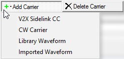
Click this button to open a ![]() drop-down menu
from which you can select a carrier to add to the setup table. The carrier
is inserted above the currently selected row in the table. The maximum
number of carriers is 16.
drop-down menu
from which you can select a carrier to add to the setup table. The carrier
is inserted above the currently selected row in the table. The maximum
number of carriers is 16.
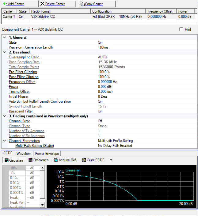
Click this button to delete the currently selected carriers in the setup table. You can highlight multiple carriers for deletion by holding down the CTRL key. You can also use the SHIFT key to select a succession (group) of carriers.
Click this button to quickly add a copy of the selected carrier to the last row in the setup table.
Double-click or use the drop-down menu to control the operating state of the carrier.
Range: 10 to 10240 ms
Step: 1 ms
Default: 100 ms
Sets the waveform generation length.
Choice: AUTO | 1 | 2 | 3 | 4 | 5 | 6 | 7
Default: AUTO
Double-click or use the drop-down menu to set the oversampling ratio.
If you select AUTO, the signal generator automatically sets an optimized oversampling ratio for the current setup.
The Total Sample Points value is automatically determined based on the oversampling ratio. Using a larger oversampling ratio results in a more completely filtered image, but also uses more waveform memory by increasing the number of waveform points. In the case where the System Bandwidth = 1.4MHz, Auto = 2, else Auto = 1.
Base Sampling Rate is a sampling rate without Oversampling Ratio (OSR).
There is a relation among Base Sampling Rate, OSR, Total Sample Points, and Waveform Generation Length as follows.
Total Sample Points = Base Sampling Rate (MHz) x OSR x 1000 x Waveform Generation Length (ms)
Example: System BW = 5 MHz, OSR = 1 (Auto), Waveform Generation Length = 10 (ms) case:
Total Sample Points = 7.68 (MHz) x 1 x 1000 x 10 (ms) = 76800 (Points)
The software sets Base Sampling Rate based on System Bandwidth (BW) as follows:
System BW = 1.4 MHz, Base Sampling Rate = 1.92 MHz
System BW = 3 MHz, Base Sampling Rate = 3.84 MHz
System BW = 5 MHz, Base Sampling Rate = 7.68 MHz
System BW = 10 MHz, Base Sampling Rate = 15.36 MHz
System BW = 15 MHz, Base Sampling Rate = 23.04 MHz
System BW = 20 MHz, Base Sampling Rate = 30.72 MHz
When Carrier Aggregation has multiple carriers, Base Sampling Rate = 30.72 MHz.
View the waveform length, displayed in points. You cannot edit this cell.
Total Sample Points is directly related to the Oversampling Ratio value selected. Increasing the oversampling ratio increases the total sample points. See the online help for more information.
Range: 10.0 to 100.0 %
Default: 100.0 %
Set the clipping (limit) level of the I/Q waveform before filtering.
100.0% = no clipping.
Range: 10.0 to 100.0 %
Default: 100.0 %
Set the clipping (limit) level of the I/Q waveform after filtering.
100.0% = no clipping.
Sets the frequency offset for the carrier relative to the signal generator’s frequency setting.
The range of the parameter is coupled to Oversampling Ratio, Base Sampling Rate, System Bandwidth, and the max ARB Sample Clock of the connected signal generator.
In the case (1) or (2), auto configuration is done for Frequency Offset.
(1) When any action, “Add CC”, “Delete CC”, “Copy CC”, or Change System BW is done, and Auto Carrier Aggregation Configuration is on.
(2) When Auto Carrier Aggregation Configuration is changed to on from off.
If Auto Carrier Aggregation Configuration is set to off, auto configuration does not work.
Range: -60.000 to 0.000 dB
Default: 0.000 dB
Sets the power level in dB for the selected carrier in a multiple carrier configuration, relative to the power settings defined for the other carriers in the configuration.
Note: You can ignore this parameter for single carrier configurations.
In single carrier configurations, the amplitude of the signal is determined by the Amplitude setting in the Instrument node.
See the online documentation for more information.
Range: 0.000 to Minimum (Waveform Generation Length - 1 ns or 10 ms - 1 ns) (us)
Default: 0.000 (us)
Specifies the length of timing offset.
The maximum value of the range depends on Waveform Generation Length.
If Timing Offset cannot be divided by sampling period (1 / Base Sampling Rate / Oversampling Ratio), it is rounded to the nearest sample point.
Range: 0 to 359 degrees
Default: 0 degrees
Set the initial phase of the carrier.
Choice: On | Off
Default: On
Double-click or use the drop-down menu to turn the auto symbol rolloff length configuration on or off.
Range: 0 to 400 Ts
Default: 15 Ts
The cyclic prefix used with SC-FDMA modulation in LTE results in a discontinuity between SC-FDMA symbols. Windowing is used in the Signal Studio for 3GPP LTE software to reduce spurious signal generation between symbols caused by this discontinuity. Symbol Rolloff sets the windowing length in Basic Time Units. Adjusting the Symbol Rolloff Length can improve ACPR performance, however this may result in degraded EVM performance.
Basic Time Unit (Ts) = 1/(15000 x 2048) seconds
Choice: On | Off
Default: On
Double-click or use the drop-down menu to turn the baseband filter on or off. In most testing conditions, Keysight recommends using the baseband filter (Baseband Filter = On) to achieve a balance between ACPR and EVM performance.
Choice: Off | On
Default: Off
Double-click or use the drop-down menu to turn the channel on or off.
Choice: Mobile | Static
Mobile is not available in this Signal Studio release.
Displays the number of transmitter antennas.
Displays the number of receiver antennas.
Multi-path Profile Setting
This parameter is active when Channel Type is set to Static.
Click the button in the cell to open the Multipath Configuration window, which enables you to add up to 20 paths with delay, power, and phase impairments to simulate the multi-point reflection experienced in a real-world multipath environment.
The graph view displays several different representations of the generated waveform. For more information, see Graph View.